4.8. Exercise: Wiring Diagrams#
4.8.1. Instructions#
Complete the pre-watch.
Read the information below.
Answer the following questions.
4.8.2. Pre-Watch#
Wokwi Documentation
Read the Wokwi diagram editor documentation here:
https://docs.wokwi.com/guides/diagram-editor
Wokwi Hardware
A list of supported hardware in the Wokwi simulator is available here:
https://docs.wokwi.com/getting-started/supported-hardware
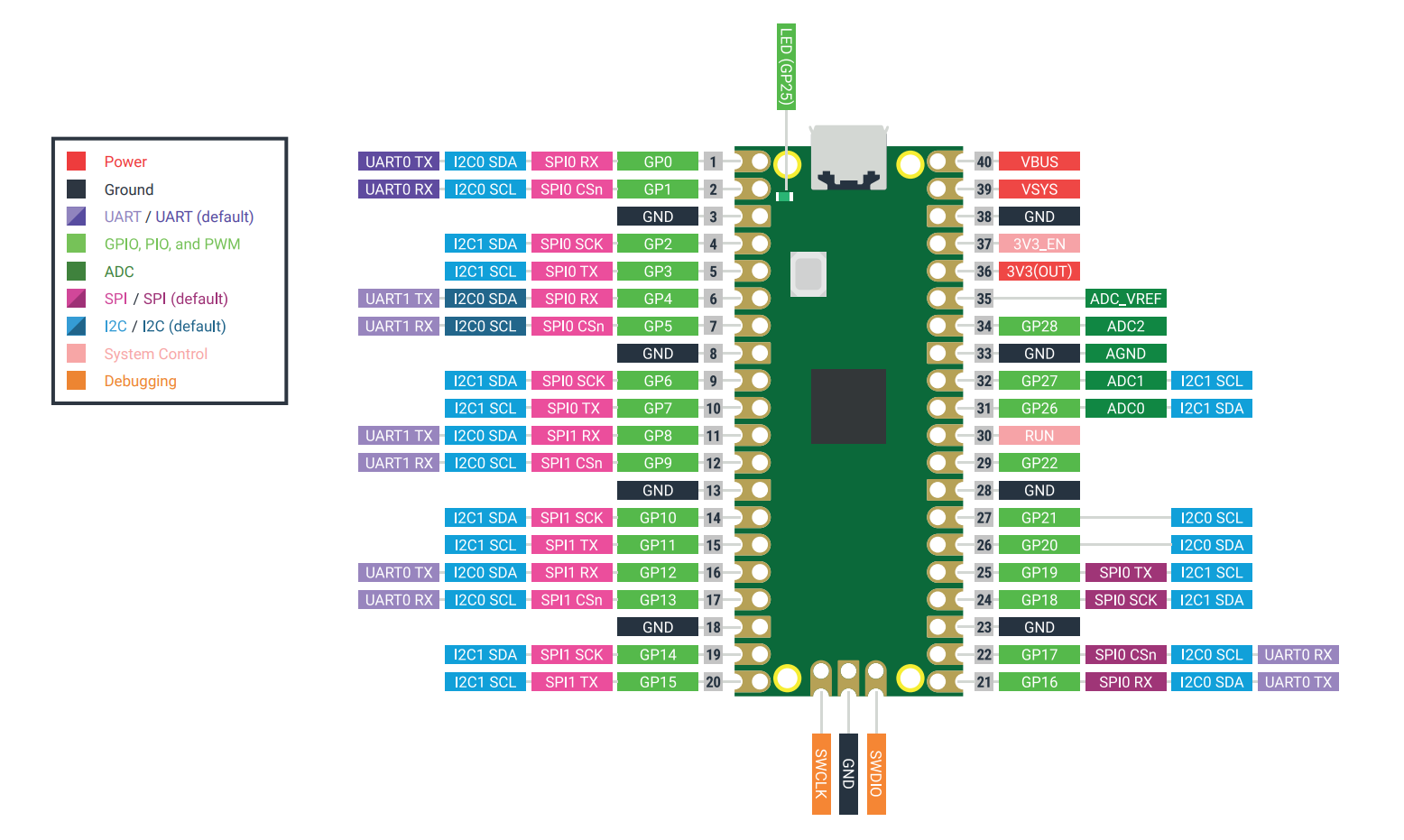
Raspberry Pi Pico Pinout
Use the pinout diagram below to help you answer the following questions.
Question 1
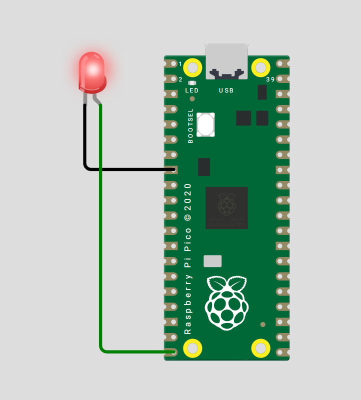
Draw a wiring diagram where the Raspberry Pi Pico drives a red LED.
The circuit should include:
The LED anode, or kinked leg, connected to GPIO 15 through a \(220 \ \Omega\) resistor.
The LED cathode, or straight leg, connected to ground, GND.
Put an image of your diagram in the answer box.
Solution
Any GND pin on the Raspberry Pi Pico can be used for the LED cathode connection.
Question 2
Draw a wiring diagram where the Raspberry Pi Pico controls a servo motor.
The circuit should include:
Servo signal pin connected to GPIO 16.
Servo power pin connected to 3V3.
Servo ground pin connected to a GND pin.
Put an image of your diagram in the answer box.
Solution
Solution is locked
Question 3
Draw a wiring diagram where the Raspberry Pi Pico is connected to an MPU6050 sensor.
The circuit should include:
MPU6050 SDA pin connected to GPIO 4.
MPU6050 SCL pin connected to GPIO 5.
MPU6050 power pin, VCC, connected to 3V3.
MPU6050 ground pin connected to a GND pin on the Raspberry Pi Pico.
Put an image of your diagram in the answer box.
Solution
Solution is locked
Question 4: Extension
Write matching MicroPython code for each of the previous questions to interact with the components.
Include code for:
Blinking the LED connected to GPIO 15.
Moving the servo connected to GPIO 16.
Reading data from the MPU6050 connected using I2C on GPIO 4 and GPIO 5.
Solution
Solution is locked